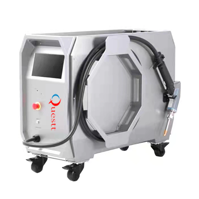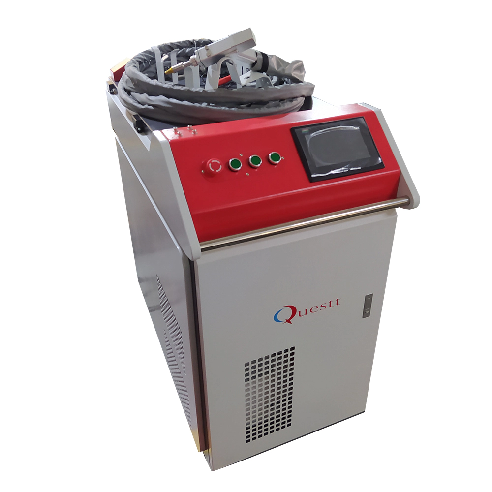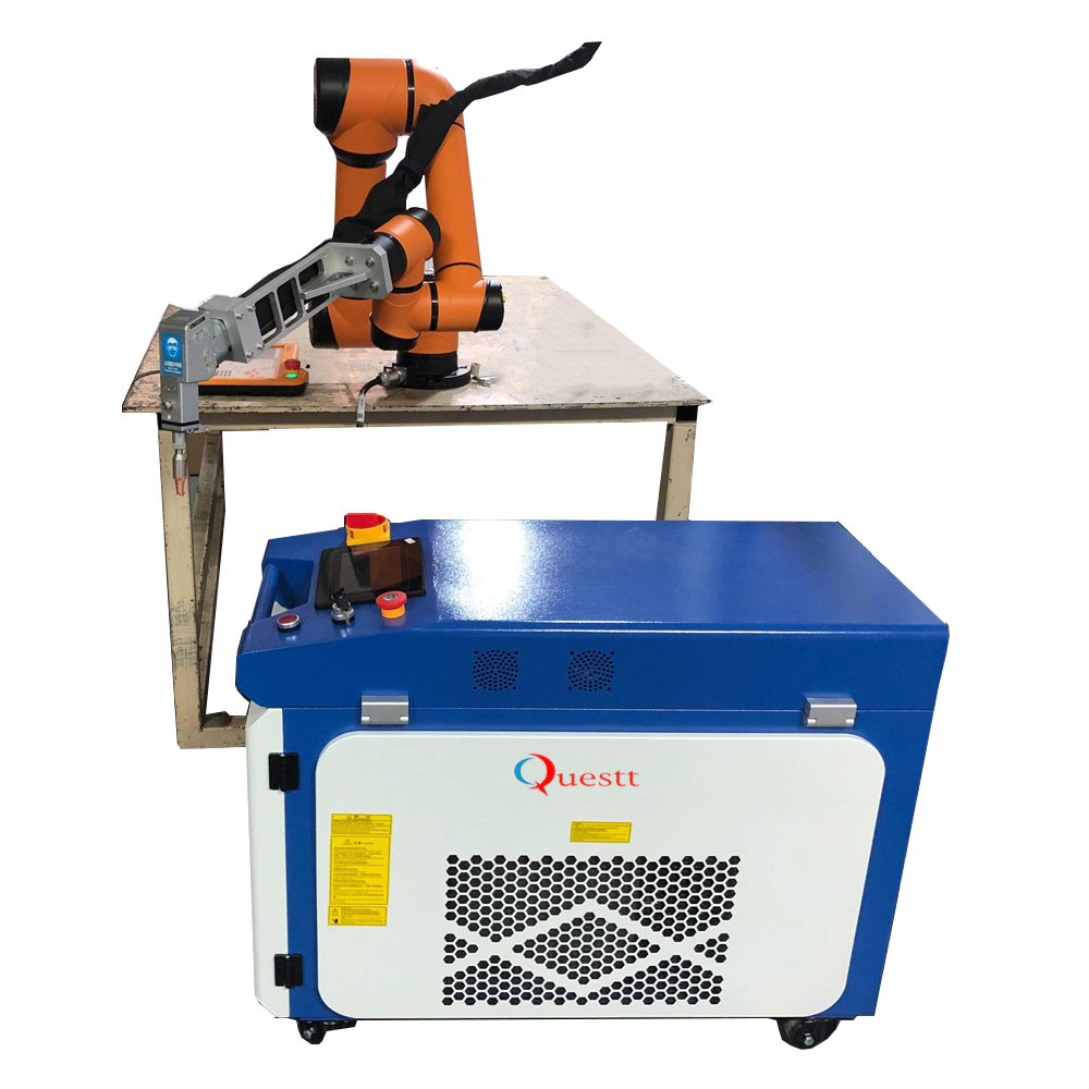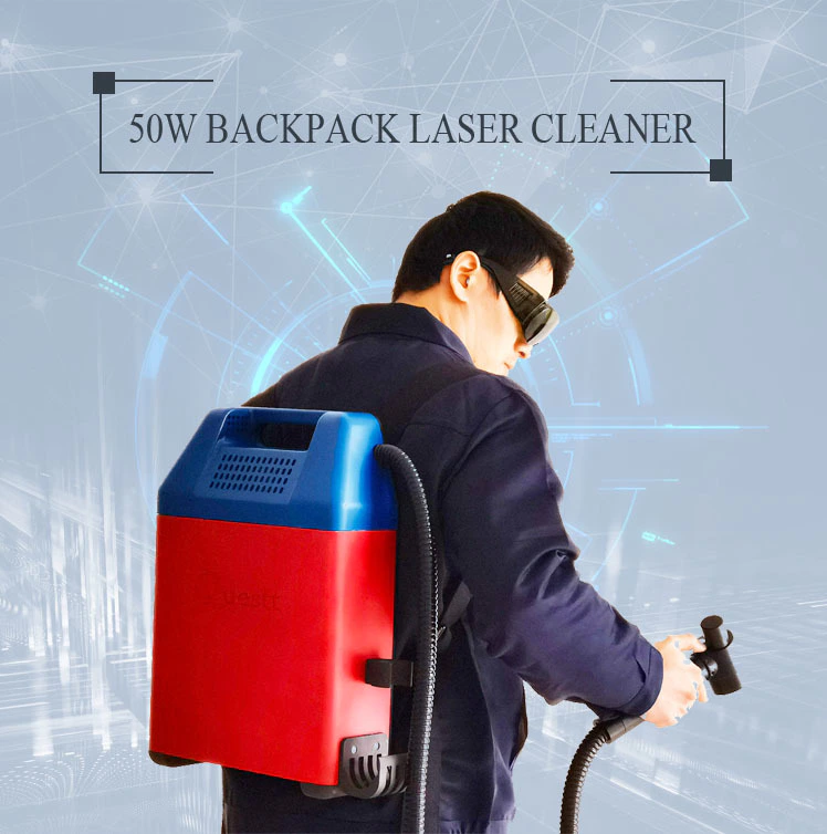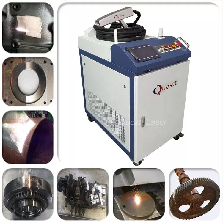

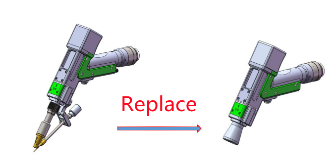
One machine, three functions( welding, cleaning, cutting)
The MicroSlice V1 | a Tiny Arduino Laser Cutter
by:QUESTT
2020-04-10
I saw an instructure a few years ago and Groover used a pair of DVDs
RW drive for making pocket laser engraver.
Inspired by this idea, driven by a full set of recent purchases
The CO2 laser cutting machine with size 50 W, at the start of the micro controller competition, I decided to make a breakthrough in making my own mini laser engraving.
I call this project MicroSlice.
What are the features of MicroSlice?
MicroSlice won the Grand Prize of the 2013 radiosack single chip contest!
Thank you so much to everyone who voted and of course very much to Radioshack for the super award :)
Micro slice v2.
6 the following affiliate links can now be used here | when purchasing. Thanks :)eBay. com | eBay. co. uk | eBay. fr | Amazon. co.
The basis of the Groover shaft is the two micro stepping motors on the DVDRW drives.
The motor drives the DVD head mechanism of the moving laser cutting head or cutting table.
My first starting point was to find a similar set of motors and a recycled laser diode.
But I want a slightly different design.
Where Groover has the cutting table move on the y axis, I want a fixed cutting table.
To do this, I got inspiration from the gantry crane.
Since the cutting table is fixed, the cutting head must move along the y-axis, but it must also accommodate the x-axis.
Therefore, the entire cutting head and x-axis must move along the y-axis.
Just like the gantry crane moves up and down the dock.
So I need two stepping motors with threaded shaft.
The longer the axis, the greater the potential workload
The area of the cutting head.
I also need one or more runners to get the y axis gantry to move forward.
In short, I can\'t find what I want from the DVD
I found the RW drive.
The stepping motor does not have thread bolts that can move along the threaded shaft, the laser diodes are firmly pressed into their housing and I am unable to remove them from the DVD
RW without causing damage.
So in the end, I turned to the old faithful eBay to find the parts.
1 x Arduino UNO R3 1 x axis Motor 1 x y axis Motor 1 x double relay 2 x easydrive 2x5 v low voltage difference 1x3. 3 V low pressure difference 2 x heat-
1x45x10 fan (12v)
4 x stop switch 9 x magnet 4 x rubber foot 5 x thumb screw 1 x laser socket 1 x laser module 1 x Laser Driver 1 x laser lens 1x4mm aluminum tube 2x3mm 150mm steel rod 1 x 3mm x 100mm steel rod 17 x M3 micro Rod 6 x M2 sink head (6mm)
6 x M2 nut 6 x M2 pot-head (6mm)8 x M2 Pan-head (8mm)
4 × M3 nylon screws (6mm)
4 x M3 50mm stand 7 x M3 cap-Head Screw (8mm)
8x M3 3mm nylon gasket 97 x laser-cut parts!
The micro-slice parts are arranged to be laser cut out from two plywood or acrylic sheets of 3mm x 400mm x 300mm.
A zip file is attached below.
The micro-slice uses a 300 mw 635nm laser diode.
It will hurt you if you are not careful.
Please pay attention when processing laser.
Don\'t look at the beam, don\'t point it to yourself or anyone else.
Don\'t be an idiot.
Where do we start?
First, we need to build a data;
Points for all other measurements.
I will use the motion range of the x-axis motor and the distance between the two ends of the stepping motor shaft as our benchmark.
I chose this because we need to align the middle of the range with the center of the cutting table.
From there we can measure the position of the three bolt holes of the stepping motor, and we can also set the height on the cutting table.
The motor is fixed on the back plate that will be removed and disposed.
There must be several features of the gantry;
It must be able to connect the x-axis motor and it must provide a cross shape
Bar stability slider, somewhere in the laser module, it must also have runners in the y-axis.
Since I will cut the parts from 3mm plywood, I will use vector graphics to design the parts.
There are several programs that can help you with this part.
Inkscape is an open source vector graphics editor that works on several platforms including Linux and Raspberry Pi.
The gantry will run along two ground steel bars of 3mm x 150mm.
There will be two sections of 4mm aluminum pipe pressure on the rod in the gantry.
The steel bar will bear the weight of the Assembly, which means that the motor only needs to handle the position change without having to fight the weight.
There are a total of ten different versions of the gantry, and the tenth version is part of the final version.
I kept it simple at first;
Install the motor, get the correct height on the cutting table, and make sure it is wide enough to manage the full length of the x-axis.
Every new iteration of the gantry adds something new, or corrects an error, or the most common case is that both are added;
Improve and add to the design.
Version 1: Add the motor and set the height and width.
Version 2: reduce weight by cuttingouts.
Version 3: Correct.
Version 4: increase the depth of the lower cross-
The bar is from 15mm to 30mm to increase stability.
The weight of the laser module causes the gantry to tilt forward and bind to the runner.
Version 5: added space and bolts to the end of the x-axis-stops.
Version 6: Correct.
Version 7: added space and bolts to the end of the y-axis-stops. Version 8: Cut-
The output on the lower beam allows the y-axis stepping motor gap.
Version 9: added brackets for the cable.
This was used during the first drying
Operation of micro-slices.
Version 10: corrected. Final version.
There are two main uses of gantry platform:
Support The Knife of the gantry and install the y axis motor.
Design constraints are limited to the width of the gantry and the travel length of the y-axis.
I want a lightweight platform for the gantry and I also need to install the cutting table.
Everyone likes to have a honeycomb cutter on their laser cutter and I think there should be one for the micro-slice.
To get the extra strength, I used two layers of 3mm sheets to bond together.
Each end has two teeth and they lock each other with the two sockets on the gantry platform to prevent the cutter from moving.
I pressed some nd magnets on the cutting table to help keep any paper safe when Engraving/cutting.
The area exposed to the laser is covered with thick aluminum foil.
This will protect the table from the heating of the laser. The heat-
The receivers of two LDOs come from a single recovered BGA heat-sink.
1 | heat dissipation-
Old BGA package for Sink. 2 | Add 2.
Two LDOs have 54mm pins.
3 | archive the pins on the lower side of the PCB.
4 | cut off heat-
Sink into strips.
I measured the width of LDOs and cut a strip along the straight line of the screw hole.
Later we will use the screw holes to install the LDOs onto the microchips.
5 | shorten the belt to match the low voltage difference.
6 | clean the edges and remove black from the surface that will connect the low pressure difference.
7 | stick LDOs to heat-
Sink using a heat conducting adhesive.
8 | allow the glue to set.
You can also bring the connection LDOs using hot glue.
Since then, I have found a new heat source.
Hui, Instructure can check the parts list at the beginning of this year.
The lower layer is equipped with electronic equipment and supports the gantry platform.
The bottom plate has dual relays for Arduino and fans and lasers.
There is a low voltage difference of 5 v on the upper board to power the fan and a 3.
3 v low voltage difference driving the laser.
There are two EasyDriver motor controllers in front of LDOs that will manage the stepping motor.
Arduino and dual relays are mounted on the 3mm M3.
I found that screw.
The holes near the reset switch on the Arduino are too close to the connector to screw!
I have attached some double shims
Double sided tape for Arduino and base-plate.
I will show you at the last Assembly how all of this is combined.
I want to make sure everything is OK before I submit the final version;
So I assembled all the parts, installed the electronics, and started connecting them together.
I used ribbon cables and DuPont connectors in cabling.
I would definitely label all the wires with tape so I wouldn\'t forget where all the wires went.
Since I\'m going to use Arduino with Grbl, I can use their guide to help me connect the microslices correctly. Mid-
I had a problem throughout the building;
EasyDrivers is too close to the Arduino below.
I had to move the PCB further in order to make room.
I didn\'t regroup everything together because I expected more complications, so I took all the electronics off the top board.
Easydriver requires a higher voltage than the voltage provided by USB.
I am using the 12 v PSU connected to the DC jack on the Arduino.
And then there\'s a Vin pin-
On the motherboard I can power off to EasyDrivers and two LDOs.
Easydriver needs to be configured for micro-stepping.
Simply cut the standard step into smaller steps.
MS1 and MS2 pins on EasyDriver are connected to on-
We can set the breakdown to 8.
That means we can now get 160 instead of a 20-step revolution.
For more details on EasyDriver access to schmalzhaus. com/EasyDriver.
I put some masking tape on the wood to reduce the laser burn and burn.
This does mean that I have to spend a few more minutes peeling it off after it has been cut.
I have used the pva glue and fixed it together with a clip where I can.
The gantry has to do almost all the work at once before the glue is dry, so that it can be laid flat to prevent it from twisting.
I screwed about 50mm of the bolts through the lower board and used them as guides to assemble the columns.
It also keeps everything Square when the glue drops.
The cutting table is covered with some thick aluminum foil.
The magnet is pressed in and a masking tape is pasted on the area without foil.
Then press the aluminum on the table and cut off the excess with a knife.
Keep the wire short to make sure there is no short circuit.
I chose a 12 v fan and will power it with a 5 v low voltage difference.
We want a big slow.
The amount of air moving, not fast lowvolume.
Keep the wind-
Low speed helps keep things on the cutting table.
I follow the connect Grbl section on the Grbl Wiki to connect the microslices.
The fan relay is connected to the coolant pin (A3)
, Laser diode relay to the spindle on/off pin (12).
The MicroSlice uses Grbl VMPA.
8 for motion control.
Grbl conversion G-
The code in the command understood by the EasyDriver stepping motor controller.
We need another program to send G-
I will use the Grbl controller v3 of Zapmaker. 0.
Before you start, you need the Arduino IDE that is available on the Arduino website.
Make sure the laser diode is not connected to the power cord when configuring the micro-slice.
If connected, the laser will be turned on and off during setup and configuration.
The laser diode is connected only when you are ready to cut or carve.
Grbl\'s wiki shows you how
Compile the Grbl hex file onto the Arduino.
For those of you who have Raspberry Pi like me, you will be happy to know that you can use your Pi to control the slice!
Zapmaker has graduallyby-
Step Guide for installing Grbl controllers on Raspberry Pi.
We need to generate some G-Code.
The best way to do this is to combine Inkscape with the laser engraving pluginin.
Vector graphics editing with open source, similar to Illustrator, CorelDraw, or Xara X, using W3C standard Scalable Vector Graphics (SVG)file format.
I have been using the same plugin.
In Groover\'s work for his sculptor, he made a short film detailing its use.
We use the new G-
We need to configure the code for Grbl to use the stepping motor and terminalstops.
You can use the Arduino IDE serial terminal (
CTRL Shift M)
Send commands to Grbl.
Send $ Display configuration settings to Grbl (
You may not look the same); $0=755. 906 (x, step/mm)$1=755. 906 (y, step/mm)$2=755. 906 (z, step/mm)$3=30 (
Step pulse (usec)$4=500. 000 (
Default feed, mm/min)$5=500. 000 (
Default seek (mm/min)$6=28 (
Step port reverse mask, int: 00011100)$7=25 (
Step idle delay (msec)$8=50. 000 (
Acceleration, mm/second ^ 2)$9=0. 050 (
Connection deviation (mm)$10=0. 100 (Mm/segment)$11=25 (n-
Arc correction, int)$12=3 (n-decimals, int)$13=0 (
Report inch, Boolean)$14=1 (
Automatic Start, Boolean)$15=0 (
Reverse step enable, bool)$16=0 (
Hard limit, Boolean)$17=0 (
Cycle of automatic search, Boolean)$18=0 (
Int dir reverse mask, int: 00000000)$19=25. 000 (
Feeding (mm/min)$20=250. 000 (
Finding (mm/min)$21=100 (
(Msec)$22=1. 000 (homing pull-off, mm)
The setting we are interested in is $0 & $1.
These two settings configure the & Y axis.
We need to calculate the number of steps to move the cutting head 1mm in either direction.
We calculate it this way;
Number of steps = number of steps per rotation x microstep/thread spacing 20 steps-a-Turn (
18 degrees a step)
X8 micro step (
MS1 and MS2 connected to 5 v on easydriver)
/3mm thread spacing (
3mm of each trip). (20 x 8)/ 3 = 53.
333333333 so Type $0 = 53. 333 and $1=53.
333 enter the terminal to set the axis.
You need to make a soft reset in order for the change to take effect ($X).
You can also adjust Grbl using Zapmaker\'s Grbl controller.
You can access the Grbl settings through the Advanced tab.
After you click apply, you still need a soft reset.
You have to decide;
$4 = 200 this sets the default speed at which the cutting head moves while working.
$5 = 200 this sets the default speed when the cutting head moves between jobs.
$16 = 1 this makes the end-stops.
$17 = 1 this leads to the nest ($H)
, My lock is locked when I try to run the homing loop.
To enable this feature, you need to edit the source code of Grbl and recompile it. hex file.
Instructions showing how to do this are located at the bottom of this step.
$18 = 69 when executing the $ H return command, this will make the tool in the lower left corner of the cutting table zero. For an in-
See Grbl Wiki for in-depth instructions on this feature.
$19 = 200 $20 = 200 $22 = 2.
000 this sets the distance the axis is removed from the end-
Stop after the return cycle. There are in-
Deep explanation of each Grbl setting on the Grbl Wiki.
Check if your configuration is correct by typing $ in the terminal.
You should see something like this. $0=53. 333 (x, step/mm)$1=53. 333 (y, step/mm)$2=53. 330 (z, step/mm)$3=10 (
Step pulse (usec)$4=200. 000 (
Default feed, mm/min)$5=200. 000 (
Default seek (mm/min)$6=28 (
Step port reverse mask, int: 00011100)$7=50 (
Step idle delay (msec)$8=100. 000 (
Acceleration, mm/second ^ 2)$9=0. 050 (
Connection deviation (mm)$10=0. 100 (Mm/segment)$11=25 (n-
Arc correction, int)$12=3 (n-decimals, int)$13=0 (
Report inch, Boolean)$14=1 (
Automatic Start, Boolean)$15=0 (
Reverse step enable, bool)$16=1 (
Hard limit, Boolean)$17=1 (
Cycle of automatic search, Boolean)$18=69 (
Int dir reverse mask, int: 00000000)$19=200. 000 (
Feeding (mm/min)$20=200. 000 (
Finding (mm/min)$21=100 (
(Msec)$22=2. 000 (homing pull-off, mm)
The last step is to focus on the laser.
I loaded a small test sample and in this case it was an X for the sequence to run.
You can use the scale box marked as the spindle on the Zapmaker Grbl controller to turn the laser diode on and off.
There was nothing there for the first time, but with a few laps of footage, I managed to make a mark on some paper.
After that, all it needs is a little fine tuning and the laser is properly focused on the cutting table.
When I wanted to carve some 3mm plywood, I made some 3mm gasket to lift it under the lase module.
Doing so means that I don\'t have to re-focus the lens every time I want to exchange material.
Edit the source code.
During the test I found that Grbl would hang on $ H (homing)command.
I suspect this is a problem with the Z axis as there is no Z axis for the microslice.
To fix probem, we have to remove the z-axis option from the homing loop.
The command is included in the configuration.
H file in source code.
1 | from Grbl (link).
2 | open the archive file. 3 | open configuration.
In your favorite text editor.
4 | find the following code # define home_search _ cycle_0 (
1
Custom message
Related Products