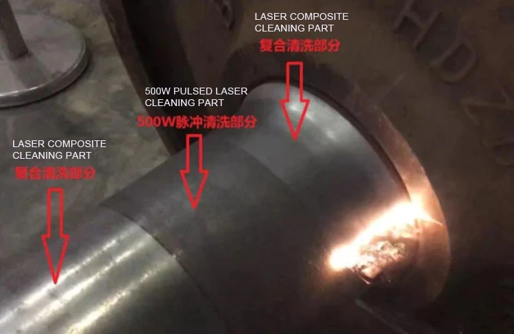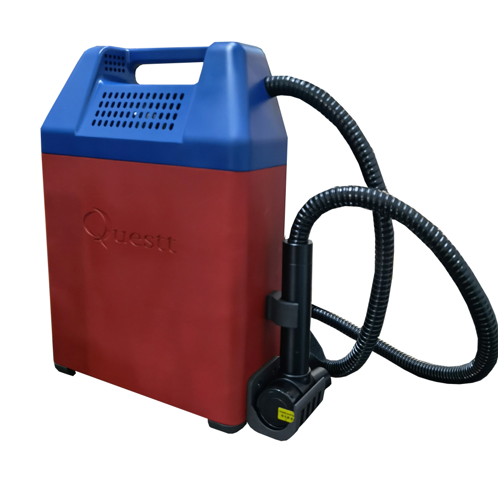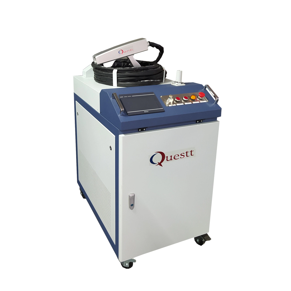


IPG 500W Laser Cleaning Machine Ready for Shipping
Raspberry Pi Motion Sensitive Camera
by:QUESTT
2020-07-17
With Raspberry Pi, Raspberry Pi camera module, PIR motion sensor, USB WiFi adapter, some parts and several Python programs, you can build a camera and when something moves in front of the camera, it will automatically take photos or record short videos and will automatically upload photos/videos to Dropbox.
This instructable shows how to build a Raspberry Pi motion-sensitive camera.
My inspiration for doing this is to help satisfy my curiosity about the behavior of my cat when I am not at home and find out the local wildlife criminals that devour the plants in my garden.
There are commercial products that can do this, but I think it would be interesting to build a product that works exactly as I wish.
The Raspberry Pi performs a Python program that starts when the Raspberry Pi is started and waits for the motion to be detected by the PIR sensor.
When motion is detected, the Raspberry Pi takes a photo or records a short video and then uploads it to the DropBox account.
The benefit of uploading to Dropbox is that the owner of the Dropbox account can view photos and videos on any device (
Laptop, desktop, tablet, smartphone)
From anywhere with Internet access.
After the upload is complete, the program sleeps for a few seconds and then waits again for motion to be detected.
There is also a second, running Python program that monitors the switch on the side of the camera.
This program illuminates an LED in the switch so you know when the camera is working.
When the program detects pressing the switch, it flashes the LED in the switch and then stops the software in the Raspberry Pi.
The LED in the switch is off, indicating that it is safe to unplug the camera power supply.
An additional LED is installed on one of the side panels, and when the Raspberry Pi is connected to the power supply, it is illuminated.
A more detailed explanation of how the software works is provided in Step 20.
The wiring of each component to Raspberry Pi is shown in the figure.
The housing of the camera is cut with a birch plywood of 1/8 thick with an Epilog spiral laser cutter.
This note assumes that you have basic experience in setting up and running Raspberry Pi, that you have welding experience and that you can use a laser cutter.
This is what I did at TechShop.
The following parts are required to build a Raspberry Pi motion sensitive camera: Raspberry Pi part: PIR sensor part: Raspberry Pi camera part: shutdown switch part: power indicator part: Housing Part: bottom panel part: panel USB cable: Power supply: miscellaneostols (not pictured)
: Equipment for installing Raspberry Pi software (not pictured)
: The first step is to cut the parts of the shell from 1/8 of the paper \"(3mm)birch plywood.
TechShop\'s 45 W Epilog spiral laser cutting machine is used to cut and carve parts.
All shell parts can be cut from a 24 \"x 18\" sheet of plywood.
The design is shown in the first chart.
Cutting black wire with laser cutting machine;
The blue line will be etched using a low power cut;
Will engrave green words;
The red line won\'t be cut-
Include them to show the outline of the part.
I use the color mapping function of the laser cutter to specify the settings for cutting and engraving.
The settings used are displayed on the right side of the color map screen shot.
Photos 1 and 2 show all the parts completed together.
The separate sections are: Photos 16 and 17 show close-up of the cutouts of screws and nuts that will be used to secure the housing together.
Steps 13 describe how these are used.
Gently polish with 120 sandpaper to remove burn marks left by the laser.
The laser cut design file is located in the ZIP file attached to this step.
This document contains CorelDraw (. cdr)
And package PostScript (. eps)
Files for design and files for loading color mapping data for laser cutting machines.
For more information on how to use color mapping, see page 113.
Use the following sections: button switch (photo 1)Jumper (photo 2)
, 470 ohm resistance (photo 3)
And heat shrink tube (photo 4)
, Prepare the switch: The completed switch is shown in Figure 17.
Use the panel to install the LED to start the Assembly of the LED power indicator (photo 1)
And a resistance of 470 ohms (photo 2).
Photo 16 shows the completed LED power indicator.
Assemble the left panel as follows: the left panel is now complete.
Assemble the right panel as follows: the right panel is now complete.
Assemble the bottom plate as shown below: The finished bottom plate is shown in Figure 7.
In this step, you will create a Dropbox platform application.
Creating the app will allow the Raspberry Pi motion sensitive camera to upload photos and videos to your Dropbox account.
If you don\'t already have a Dropbox account, create it.
Click the \"register\" button.
If you already have a Dropbox account, please log in to Dropbox.
The first step in preparing the Raspberry Pi is to install and configure the Raspberry Software: The second step is to download the Python program that controls the shutdown switch, which takes pictures or takes pictures when motion is detected.
Create the directory where the Python program will reside, and the directory where photos and videos will be stored using these commands: issue the following two commands to get the Python program: Step 3 is to install the Dropbox uploader, and configure it using the application key and application secret in step 8 \"create Dropbox Platform Application.
Install uploader using the following command: if this command fails, you will need to install git using the following command and then reinstall
Git clone command above: after installing Dropbox-
Upload from git, change to Python program directory using the following command: configure the Dropbox Upload program by executing the following command: you should ignore the five things listed on the screen --
You did these in step 8 of this structure.
What you need to do is enter the application key and the application secret from Step 8 and select \"a\" for the permission type \"(
See the first arrow on Screenshot 1).
After clicking enter on the permission type, you will be instructed to enter the URL in your browser (
See the second arrow on Screenshot 1).
Write down the URL carefully, enter the computer with a web browser, and then enter it.
Once entered, the web browser will display a page asking you to allow the app to access the folder on the Dropbox (screenshot 2).
Click the Allow button.
The next page displayed will let you know that the app has successfully connected to the Dropbox (screenshot 3).
Follow the instructions on the Raspberry Pi screen and click Enter \".
You will be confirmed, as shown in Screenshot 4, the settings are completed on the Raspberry Pi.
If it fails, it is likely that it is due to an error in the application key, application secret, or URL entry.
Try again by typing the above command and re-
Enter information.
Next, test the connection to Dropbox by issuing a command: this command will send a file to Dropbox that contains the IP address of the Raspberry Pi.
The output of the command is shown in Screenshot 5.
You should find the files in the App folder of your Dropbox account.
The fourth step is to configure the Raspberry Pi to work with your wireless network.
Edit the file \"wpa_supply.
Conf \"command: add the following line at the bottom of the file, replace the name and wifi password of the wifi network, as shown in the figure, and save the file.
If you are not familiar with how to use the Nano editor, howtogeek has a good guide for nano beginners.
The file should look like shown in Screenshot 6.
For more details on how to configure Raspberry Pi for different types of wifi networks, visit the Sparkfun website.
Step 5 is to configure the system to start a Python program that monitors and lights the shutdown button during the system startup.
Edit the file \"rc.
Local with command: before the line that represents exit 0, add the following line command to the bottom of the file and save the file.
The file should look like the file in Screenshot 7.
Step 6 is to configure the system to run the Python camera program when the WiFi on the Raspberry Pi is up and running.
When the Python camera is running, it waits to detect motion and then takes a photo or short video and uploads it to the Dropbox.
The command to start the program is placed in the \"etc/network/interfaces\" file.
Edit the file with the command: If you want the camera to take a picture, add the following command at the bottom of the file: If you want the camera to record the video, add the following command to the bottom of the file: screenshot 8 shows what the file should look like when configured to take a photo.
The configuration of the raspberry is now complete.
The last step is to turn off the Raspberry Pi with the command: After the Raspberry Pi is turned off, disconnect all the cables but leave the SD card in the socket on the Raspberry Pi.
Use 2 M2 machine screws, 2 M2 washers and 4 M2 nuts (photo 2)
Installation of PIR sensors (photo 3)
To the front panel (photo 1)
As shown in Figure 7, the PIR sensor installed.
Using two 3/4 \"#4-
40 machine screws, nuts and nylon gaskets (photo 1)
, Install the Raspberry Pi on the front panel as shown below: use 4 M2 10mm machine screws, 4 M2 washers, 12 #4 flat nylon washers and 4 M2 nuts (photo 2)
Install the Raspberry Pi camera (photo 1)
As shown below: the full front panel with PIR sensor, camera and Raspberry Pi is shown in photos 8 and 9.
Case of Raspberry Pi motion sensitive camera with #4-
40 1/2 \"machine screws and nuts: no adhesive required.
The way to do this is to thread the nut on the Screw (photo 2)
, Install the panel together (photo 1)
Put the screw in T-slot (photo 3)
Gently tighten with a screwdriver while holding the nut with your finger.
When the whole case is combined in this way, it is very strong.
Now assemble the boxes the following way: the boxes should be securely secured together and look like photos 15 and 16.
In step 18, the rear panel will be connected to the shell.
Since most of the boxes are assembled (photo 1)
It\'s time to start connecting components.
Connect one of type A male USB connectors type A female USB connectors on Raspberry Pi (photo 2).
This USB connector will be used to connect the USB WiFi adapter to the Raspberry Pi.
Connect the micro B male USB connector to the parent micro B USB connector on the Raspberry Pi (photo 3).
This USB connector will be used to power the Raspberry Pi.
In this step, the LED power indicator, the PIR sensor, and the shutdown switch will be connected to the GPIO pin on the Raspberry Pi (photo 1).
Photo 7 shows the Raspberry Pi motion sensitive camera that completes all internal wiring.
Connect the antenna to the USB WiFi adapter as shown in the figure.
Set up and test Raspberry Pi motion sensitive camera as follows: Test camera: Setup and test is now complete!
The last step in building a Raspberry Pi motion-sensitive camera is to connect the back panel.
The Raspberry Pi motion sensitive camera is now complete!
Photos 1 to 7 show the camera is running.
If the camera will be used where it is inconvenient or is unable to get power from an AC outlet, a 5 volt 1 Amp USB battery pack can be used (photos 8 and 9).
According to Adafruit, the power pack in the photo will power the \"headless\" Raspberry Pi (
No keyboard, mouse, display connection)
Plug the mini WiFi adapter into the USB port for about 7 hours.
Two client Python programs are used in this instructable to create Raspberry Pi motion sensitive cameras. rpi-ms-camera.
The first program \"rpi-ms-camera.
Py \"is started by the command: in the system File\"/etc/network/interface. The \"post-
When the network interface is up and running, run the \"up\" command.
Listing 1 to 6 shows the source code of the rpims-camera.
Py program: Line 4-26 (listing 1)
Import the required Library and define the constants used in the program. Lines 28-31 (listing 2)
Define the \"generate_file_name\" function.
This function is used to generate unique file names based on date and time.
This file name will be used for photos or videos.
The generated name format is \"yyyy-mm-dd-hh-MM-ss-
Tz \"yyyy is year, mm is Month, dd is day, hh is hour, MM is minute, ss is second, tz is time zone. Lines 33-46 (listing 2)
Define the \"motion_detect\" function.
This function is called when motion is detected by the PIR sensor.
This feature can take photos or record videos, upload photos or videos to Dropbox and delete files from Raspberry Pi. Lines 48-53 (listing 3)
Define the \"snap_photo\" function.
This function is used to take pictures. Lines 55-64 (listing 3)
Define the \"recor _ video\" function.
This feature is used to record videos. Lines 66-74 (listing 3)
The \"Upload _ to_dropbox\" function is determined.
This feature uploads the specified file to Dropbox. Lines 76-85 (listing 4)
Define the \"uplo_ip_address\" function.
This feature is used to create a file with a Raspberry Pi IP address and upload it to the Dropbox.
The purpose of uploading a file with an IP address is to obtain the IP address of the Raspberry Pi for debugging purposes.
With an IP address, you can use \"ssh\" to open a terminal session to the Raspberry Pi and issue a Linux command. Lines 87-91 (listing 4)
Define the \"first _ time_config\" function.
This function is called in the process of establishing the command of Raspberry Pi \"Python rpi-ms-camera. py -
\"First Time\" issued.
This command is used for step 9 of this structure. Lines 93-99 (listing 4)
Define the \"test_dropbox\" function.
This function is established during the call process. raspberry used to command \"Python\'s rp-ms-camera. py -Issue \"test \".
This command creates a test file containing the Raspberry Pi IP address and uploads it to the Dropbox.
If it successfully sends the file, then the Raspberry Pi has been set correctly to be used with the Dropbox.
It is used in Step 9 of this structure. Lines 100-133 (listing 5)
Is the beginning of the main program. Lines 135-164 (listing 6)
Performs initialization of the main program. Lines 152-163 (listing 6)
Is the main loop of the program. Lines 159-163 (listing 6)
For debugging purposes.
These rows are executed if the program is running from the command line and Ctrl/C is pressed to stop it. rpi-halt-btn.
The second program \"rpi-halt-btn.
Py \"is started by the command in the system file during startup\"/etc/rc. local\".
The \"&\" at the end of the command causes the program to run as a separate process that runs until the program exits.
Listing 7 shows the source code of the rpi-halt-btn.
Py program: Line 2-
Initialize the program.
Line 18 causes the program to wait to press the switch. Lines 19-
21 for debugging.
When running the program from the command line and pressing Ctrl/C, these lines will be executed. Lines 22-
26 runs when the shutdown switch is pressed.
When the Raspberry Pi is turned off, the LED on the off switch will turn off, indicating that it is safe to unplug the camera from the power outlet.
When I built the Raspberry Pi motion-sensitive camera, I thought of some improvements: control whether to take a photo or record a video. By specifying \"-p\" or \"-
\"V\" option on \"Post -\"
Up python/home/pi/pyth_programs/rpi-ms-camera.
The py command set in/etc/network/interface.
This can be inconvenient if you want to change camera mode frequently.
The way to change the mode in the current design is to use the program to put \"ssh\" into the camera, edit the \"/etc/network/interface\" file, and restart.
A good improvement is to add a two position switch to the lower part of the right panel to set whether the camera is in photo mode or video mode (photo 2).
The switch needs to be connected to Raspberry Pi and line 113-126 of \"rpi-ms-camera.
A check for py \"to delete pairs\" must be modifiedp\" or \"-v\" options.
Line 38 must be replaced by checking the value of the GPIO pin to which the switch is connected to determine what to do.
Reducing the use of the camera to trigger the side motion of the camera, I noticed that the PIR sensor is sensitive enough to detect motion from the side in addition to moving in front of the sensor.
This results in taking photos or recording videos when moving objects may not be in camera view.
The design can be improved to eliminate excess photos/videos by limiting the sensor.
This can be achieved by using 1 1/2 \"PVC bushing (photos 3 and 4)
Install to the front panel using glue or tape (photos 5 -7).
Reduce the camera\'s housing size the camera\'s housing is quite large.
The reason for the larger size is to install the connectors and cables using the USB panel.
I want to use these because I really like the idea of plugging the WiFi adapter and USB power cord into the side of the chassis.
Due to the thickness of the panel mounting cables, extra space is required inside the housing to accommodate them (photo 8).
If the Raspberry Pi is installed in a similar way to the one in my Raspberry Pi PirateBox instructable, then the case can become smaller.
In this design, the Raspberry Pi is installed near the side panel, allowing access to the USB connector of the WiFi adapter;
The power cord is inserted directly into the Pi and is extended through a hole on the side panel.
Doing this with the camera will make the case significantly smaller (photo 9).
Custom message
Related Products