I have always asserted that the assembly kit for 3D printers, laser engraving machines/cutting machines and Mills is nothing to envy for a wider range of devices --
Based on the same principles and technologies
What is sold is assembled and may be designed more carefully but not easy to control and manage.
I also believe that a good assembly of these kits is a key factor in its reliability when it comes to preparation.
That\'s why I started writing this Tutorial Guide.
After assembly, I used the GearBest laser engraving/cutter and did many tests on different types of materials (
PLA parts including 3D printing)
The result is very good.
The image for this tutorial refers to a 2500 mA laser, but the same instructions can be applied to all models of the same series, as all models are based on the same architecture for installing different power laser heads.
Thanks to GearBest, a surprise to the user.
With this coupon code, IJCDDA, you can get a 20% discount from the laser sculptor you purchased!
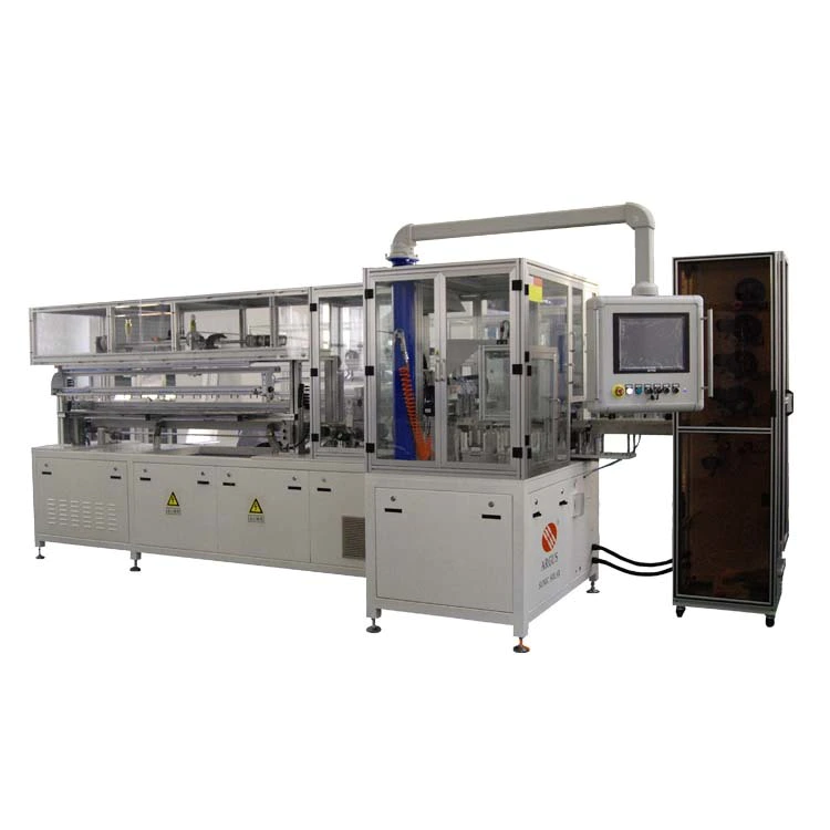
Hope it makes you happy. The kit (first image)
Includes all the components required to start the component, including the allen key.
To make things easy, I would suggest adding tools to the attached tools as well before starting the assembly work.
The box in the kit box contains three stepping motors, a cable connecting the motor to the controller, and a USB cable connecting the Arduino Nano to the computer, a controller board including Arduino and special-shaped aluminum parts, used to build a body structure.
Along with the bare parts, it is a small gift bag that includes protective glasses, a range of small test materials and several high-intensity LED lights that can be used with external USB power connectors.
Are you ready to start assembling? Go ahead! Main framework (
The base of the sculptor)
It is very easy to assemble, but you should remember to insert the M4 nut into the longer side of the shaped aluminum.
To complete this step, you will use the two longest aluminum profile parts (
Long side of main frame)
, 8 M4 nuts, acrylic front and back sides of the main frame. IMPORTANT!
Insert four M4 nuts in each side Guide of two longer brackets (
Side inside frame structure)
: There are two on the top side rail and one on the top rail.
These nuts will be used in the next steps to add the side support to the main frame and lock the Y-axis.
You will use a total of eight M4 nuts.
If you forget this simple step, you have to disassemble the frame later.
The first picture shows what you should get at the end of this step.
To assemble the main frame, you will use the longer shaped aluminum parts and the front and rear acrylic parts (
Shown in the third picture)
The following image shows the appearance of the nut after assembly and how to lock the aluminum bracket on the acrylic part.
Aluminum profile bracket (longer sides)
Should be placed vertically and locked on the acrylic side with two M4 Allen screws on both sides. Done?
Move forward to the next step. The short aluminum profile bracket is aligned with the top of the long side bracket and in direct contact with the front and rear acrylic side, contributing to the robustness and stability of the frame.
As we can see further in this way, the main frame has a boundary where a flat base can be placed and we will place the cut or carved parts on this base.
To complete this step, you will use: two short square aluminum profiles, four corner locking blocks, eight M4 10mm Allen screws and four other M4 nuts.
At this point, it is important to properly locate the short aluminum bracket to create a flat frame: this is the boundary where we can place the work plate for engraving.
Align the brackets perfectly with the other two brackets in the frame and expose them to the interior of the acrylic part front end and back end.
Each screw is then firmly locked to make the aluminum rectangular frame sturdy.
The main framework is now complete and we can continue. Go ahead!
In this step, we will assemble two control Y-axis.
To complete this step, you will use: Two stepping motors, two acrylic Y-
Shaft support, two tooth pulleys, eight M3 Allen screws.
Read before you start, keep in mind the above notes, twist the two stepping motors onto the mirrored acrylic side bracket as shown in the figure.
Then, put the pulley in place and check again if all the pulleys are correct. Done?
Prepare for the next step!
This is the first step we have to start installing moving parts.
To complete this step, you will use: Two Y-
Shaft motor set, four M3 Allen screws and nuts, four washers, four plastic separators, four bearings.
This operation is almost easy: the only thing you should consider is the correct order of the parts you should install in the Allen screws before locking the other side of the acrylic Motor support hole.
The first picture shows the block orientation bearing installed in the correct position.
The second picture shows the parts used to assemble the bearing. The third picture shows the bearings assembled correctly.
This is a matter of minutes. let\'s go next!
This is our first step in getting the pre-installed.
Assemble parts together
In this step, you will use:
Main frame of assembly, pre-Assembled two Y.
Install the other four sets of components for the four bearings.
Assembling these parts is almost an easy way;
Prepare four bearings ready to insert as shown in the first image.
Take a motor group in one hand and position it with the bottom bearing (Installed)
Corresponds to the bottom track on the longer side of the main frame, as shown in the second image.
As shown in the third image, insert the bearing and bracket with Allen screws into the top rail;
Add the gasket to the other side of the hole, just insert the nut and turn it several times.
If locked, it becomes very difficult to insert the second upper bearing.
When both upper bearings are positioned firmly, lock nut: The Motor set should be stable and move smoothly along the longer side of the main frame guide rail.
Repeat the same operation for another Motor Group.
An important step has been completed.
Are you ready for the next step?
The stepping motor uses the tooth belt we will assemble at this step to move the y axis.
Operating in the right order makes it easy to get good performance.
To complete this step, you will use: the tooth belt, four M3 Allen screws and nuts, four M4 10mm Allen screws, and four acrylic belt lock parts.
The belt will be fixed on the motor in two stages: first on one side and then the belt will be stretched correctly on the other side.
Phase 1: fix the belt on one side, as shown in the first two, prepare four acrylic belt locks: insert M3 (smaller)
Install Allen screws in smaller holes and nut on the other side.
Close it with your hands and not block.
Slide one of the two M4 nuts inserted into the frame in the step and assemble the main frame to the extreme side of the track.
Insert one side of the ribbon without cutting as shown in the third and fourth images.
It is important that you leave a few centimeters of tape outside (see the images).
If you need to adjust the belt tension or change the belt, it will be very useful in the future.
After firmly closing the M4 Allen screw, fix the side of the belt with another screw.
At the end of this operation, you will find it impossible to remove the belt.
Phase 2: fix the belt on the other side, now the tooth belt is firmly fixed on the first side, as shown in figure 5, insert it into the track and place it on the motor tooth pulley.
Don\'t be nervous now.
Apply the same method above to fix the belt on the other side.
Don\'t cut the belt now!
Before locking M3 screws (
When the belt is not completely fixed)
You can tighten your belt now.
Use the sixth picture as a guide to see the results you should get.
The belt should remain elastic if properly stretched (+/-5mm)
Avoid damage to use.
The last operation you should do is adjust the motor pulse and extract the pulley from the shaft until you see the belt almost in the middle.
Then lock both screws of the pulley.
Apply the same operation to the motorNow test on the other side to test again if the belt is stretched correctly: each motor group should slide smoothly along the main frame track without creating too much resistance.
One more step now: assemble the x-axis! The Y.
Using two synchronous stepping motors, the shaft moves along the longer side of the frame.
Now, we should assemble the support X-
Axis and laser head group, Keep Y-on both sides-
Fully aligned shaft motor.
To complete this step, you will use: four M4 Allen screws ,(last)
X-aluminum profile bracket
Shaft, two M4 nuts. IMPORTANT!
Insert two M4 nuts on the bottom side rail of the bracket: these nuts will be used for the belt locker. Align two Y-
Shaft motor set and insert four M4 Allen screws through the acrylic hole on the bracket.
Insert all four screws by hand, then complete the operation with Allen keys and lock them firmly.
Three images show the correct position of the aluminum profile bracket.
Complete this simple step? Great!
We can do more complicated things.
Assembly instructions for X-
Shaft stepping motor is the same as explained in Step 4: assemble Y-
Shaft stepping motor.
To complete this step, you will use: a stepping motor, acrylic X-on the motor side-
Shaft support, one gear and four M3 Allen screws. The X-
The shaft set has two different acrylic components: the front bracket that will carry the laser head and the rear bracket that we should assemble the stepping motor.
The step motor connector should face the top of the bracket as shown in the figure.
This will make the wiring of the motor cable easy. Already done?
It\'s not easy, but it\'s just the first part. Go ahead!
This is an almost subtle part, but fortunately it is not particularly complicated: you have learned most of the assembly methods that should be applied to this part.
To complete this step, you will use: partially assembled machine, partially assembled C-
Shaft set, four M3 Allen screws and nuts, eight bearing separators, four bearings, second acrylic X-
Shaft support and the rest of the gear belt.
Read attention before you start X-
The shaft motor and the laser head set shall be fitted with the motor facing the rear side and the laser head facing the front side.
Install the two top bearings on the two top bearings of the motor group and use one plastic separator on each side.
Refer to the suggestion of the bearing assembly explained in steps 5 and 6 and close it firmly.
See first image for proper insertion;
The second picture shows how to place the assembled group in place.
Install two bottom bearings for the second operation, you cannot pre-install
Assemble bearings.
For each bearing, insert Allen screws in the first side hole of the acrylic bracket.
Then add the three parts of the bearing, keep them in place and continue to insert the screws.
When the bottom bearings are all positioned correctly, you can turn off two Allen screws with washers and nuts.
Mounting the dental belt now that the whole structure is assembled, you can position it to the most comfortable position to assemble the dental belt, which is almost powerful.
Follow the instructions described in step 7 preparation?
Hurry up and punch, wait for the next step!
The laser head should be inserted into the relative position of the motor and does not need to be screwed to the bracket: it is just inserted in the hole.
To complete this step, you will use: the laser head and the
laser cutting machine that is almost finished.
Insert the laser head into X-
The three screws shown in the first image of the Axis Group should be adjusted to insert and firmly hold the head within the three holes on the front of the bracket, as shown in the second image.
Before inserting heat, you should adjust the three screws by hand, as shown in the third image, using any other acrylic border to align the screw depth.
After inserting the laser head, insert the wire into X-axis group.
Almost finished, there are not many steps to wait!
The controller board installation is the last component that should be added to the machine.
To complete this start, you will use: acrylic protective cover for eight M3 Allen screws, four separators, four hexagonal brackets, controller boards, control buttons, and controller boards.
Insert into the four holes of the acrylic bracket on the back, with four M3 Allen screws and four separators on the other side.
As shown in Figure 2, keep the position of the four screws inserted into the controller board.
Then lock the rear screws with the four hexagonal brackets shown in the third picture.
Prepare two button covers and acrylic controller board protection (
See picture 4)
And the position in front of the controller board.
Insert the remaining four screws by hand to maintain the position of the protective plate, then slowly rotate the button protection until they are installed inside the button switch on the controller board.
Close the four screws firmly to complete the board installation.
We\'re almost done!
The last operation before turning on the
laser engraving machine power is to connect the cable.
To complete this step and complete the assembly of the machine you will be using: two motor cables, USB cables, power supplies.
The first two pictures show how to locate the cable connector.
From left to right respectively: words of praise! ! !
The laser cutting machine is assembled.
Now you can test and enjoy with the new tool.
Note: Since there are many software applications that can meet the requirements of controlling the Arduino Nano laser cutting machine from GearBest, we will explore in a dedicated note the possibility that open source software provides the best results from this machine.